The Virtual Haptic Radar (VHR) is an extension of the Haptic Radar [1] principle and technique in the realm of virtual reality. The goal is to help (real) actors evolve and interact seamlessly with virtual scenery and virtual objects in a VR-augmented filming stage (such as a bluescreen filming stage). The previously developed Haptic Radar (HR) is akin to an array of artificial “optical whiskers” that extends the body schema of the wearer: each HR module was fitted with a rangefinder constantly measuring distances to obstacles; tiny motors vibrate accordingly, effectively informing the wearer of a potential collision (the closer the object, the stronger the vibration). The VHR is an extension of this principle in the realm of virtual reality: the wearable modules do not have a rangefinder with which to sense the presence of real physical obstacles; instead, they contain a cheap indoor positioning system that gives them the ability to know exactly where they are relatively to an external frame of reference (e.g. the filming studio). Each module also maintains a simplified 3d map of the current virtual scene that can be updated wirelessly. If the module founds that its own position is inside the force field of a virtual object, it will vibrate.
The goal is to render the wearer (an actor for instance) aware of the 3d position and relative proximity of virtual obstacles that would otherwise be only observable on the final rendering of the CG-augmented space (even if this operation is done in real time, actors cannot constantly peer on a TV monitor; and even if they could – perhaps using an invisible, tiny HMD – they presumably would not be able to form a clear understanding of the 3d space surrounding them). Thus, the VHR is conceived as a device that will help actors evolve naturally on the filming stage while avoiding virtual collisions that would create the need to re-shoot whole scenes.
Principle of operation
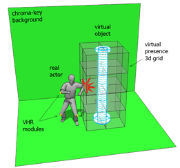
The working principle is elementary; if the module founds that its own position is inside the “force field” of a virtual object, it will vibrate alerting the wearer of this virtual presence. Each module checks its current position against a simplified 3d map of the virtual scene, namely a relatively coarse grid of cubic bins spanning the whole filming stage – see Fig.1. Each bin in the map is marked as occupied or nor, depending on the presence or absence of (a part of) a virtual object in this volume. This three-dimensional binary array is pre-computed by the external CG-rendering system, and the information is broadcasted to all the modules. With each change on the virtual scene this 3d map would need a partial, or worse, a complete update. In this first demonstration we considered a static virtual scene; however it is easy to see that even for a relatively large space, the amount of data that must be transferred remain low and can be handled by a Bluetooth or ZigBee based wireless network. For instance, if each bin corresponds to 10x10x10cm3, then 3kbits of data are needed to describe the presence/absence of objects in a 10x10x3m3 stage; using a broadcasting ZigBee-style network running at 156kbps, this means that complete scene update could be done at up to 52Hz.
Related research
Similar systems have been proposed in the past, notably [2], [3] and [4]. However, these systems do not address exactly the same kind of problem nor use the same technology: in [2], a belt like vibration system is proposed to avoid collisions with real objects whose position in space has been previously determined and communicated to the modules wirelessly (this is very similar to the HR goal, but without the rangefinders, and it thus very close to the 3d virtual map technique proposed here for virtual spaces). In [3], the application goal is the same, but wireless vibrators are used to steer actors through a virtual set; a central system is in charge of tracking the modules and sending corresponding. More close to our proposal seems [4], but there vibrotactile cues are introduced only as a support for virtual object manipulation very much along the lines of haptic feedback techniques in immersive VR environments. Instead, the VHR is a general solution that works by giving the user an intuitive (propioceptive-based) understanding of the (virtual) space surrounding him. The same principle was exploited successfully to improve navigation and confidence of gait of blind subjects using the Haptic Radar (results yet to be published).
A passive ultrasonic tracker with RF synchronization
It is important to understand that the requirements for our VHR tracking system are fundamentally different from most commercial mo-cap systems (vision based tracking systems, magnetic trackers, etc). Indeed, the following considerations lead us to consider the design of custom its hardware and software:
Each VHR module must know its own absolute position in the room, but there is no need for an external system to know the position of the modules in the room. This is quite different for instance from the marker-based approach for body tracking and motion measurement (eg. Vicom mocap system). This means that we can have as many VHD modules in the room as we want, without imposing any constraint to an external, global tracking system. The tracker must be inexpensive, in order to enable scalability of the system. Interference should be minimal or inexistent if one wants tens of modules to work simultaneously (this puts aside most non-sofisticated magnetic trackers). The modules must be invisible to the cameras (in particular, they should not emit or reflect visible light), and small (if possible, capable of being concealed under the clothing).
This basically means that the trackers have to be passive (i.e., only listening and not emitting any sort of signal, not even visible light as would do a normal “passive” optical marker). Passive electromagnetic trackers could be an ideal solution, if not for the cost (industrial indoor electromagnetic trackers systems cost in the order of thousands of dollars). We consider a cheap variant using RF signal intensity triangulation based on Bluetooth. However, the hardware was still found to be too cumbersome and expensive, and the overall system prone to external as well as inter-module interference; finally, using the intensity of the signal would not achieve sufficient spatial resolution and stability. Inspired by the body of work on ultrasound-based triangulation, we considered a variation that could satisfy our requirements. Ultrasound signal processing imposes much lighter constraints both on the receiver circuit, signal processing stage as well as the microcontroller computing power. The drawback is that ultrasound directivity may reduce the working space, a price that may be worth paying.
With these considerations in mind, we first considered optical based methods such as [5], which have been shown to satisfy all these constraints. However, we eventually preferred to develop a custom system based on ultrasonic triangulation and radio synchronization (the main reason for this choice being avoiding a complexity of the spatio-temporal structured optical beacon). Our prototype simply consists on 2 to 8 ultrasonic beacons emitting bursts every 15ms. A radio signal synchronizes receivers with the start of an ultrasound sequence. The receivers, concealed under the clothing, contain a micro-controller that computes the difference of arrival times, triangulates its own position and determines the adequate level of vibration.
We opted for a very simple time-of-flight technique (not based on phase detection), and a single ultrasound frequency (40kHz) because such ultrasound speakers were cheap and readily available at the time of the experiment. If all the beacons emit pulses that are undistinguishable from each other, then the only way to avoid ambiguities when measuring the difference of arrival times (DAT) is to send the pulses from each beacon in a sequence, adding a known time interval between the pulses that is larger than the time it takes to the sound wave to travel the maximum working distance. Moreover, without special synchronization to determine the starting time of the sequence, we need to add a special “reset” interval between the whole sequence of bursts – for instance an interval twice as large as the time between consecutive pulses of the sequence. If we want a working space of at least 5 meters, this means an interval between burst of about 5/(343m/s)=14ms, and an interval of 28ms between sequences. Considering a minimum of 3 beacons for triangulation (the locus of points with equal DAT to two beacons is an hyperbola, and we need two of these hyperbolas to determine the position – discarding of course the points that falls outside the working space), that would mean a position sampling rate of about 1/(3×14+28)70ms=14Hz. The problem with this approach is that hyperbolic triangulation is very sensitive to detection errors; moreover, it is computationally expensive.
This lead us to our final choice: emitter-receiver will synchronize thanks to a radio-signal (receiver modules know the exact times at which each beacon emits its ultrasound burst), leading to absolute triangulation. This way, the receiver will know the exact distance from each beacon; since the emitters are fixed and their position known to the modules, triangulation boils down to a simple computation of the intersection of circles centered on each beacon – in other words to the resolution of some simple quadratic equations. Although this makes each module slightly more complex, we opted for this hybrid approach (adding a simple RF receiver is much simpler compared to the complexity of a true hyperbolic triangulation system); moreover a single RF emitter can be used to broadcast the synchronization signals to all the modules each time a beacon emits its ultrasound burst (or, if the burst interval is fixed, a single RF signal is sent at the start of the sequence).

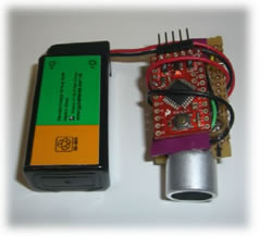
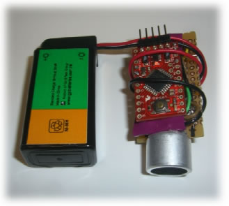
Fig. 2: picture of a single VHR module featuring an
AVR microcontroller, an ultrasound triangulation
system and an RF receiver for synchronization.
The emitter is composed of several fixed ultrasonic sources (from 2 to 8) and a radio emitter. The position of the ultrasonic sources establishes the tracking area; and their numbers will change the sampling rate of the system. The emitter circuit uses discrete electronic components, a 555 timer and logic gates. The receiver module contains discrete electronics to amplify, filter and detect ultrasound peaks, an RF receiver and a microcontroller necessary to carry on the position computation (a mini Arduino board powered by a 7.2V rechargeable battery ). The peak detector and the RF detector output are connected to different interruption pins of the microcontroller.
Each source emits an ultrasonic burst every 15ms, one after the other in a never-ending loop. This establishes a maximum working distance of about 5 meters. The radio emitter sends a synchronization signal each time the first source is activated. The ultrasonic and radio receivers are connected to the interruption pins of the Arduino board (pins 2 and 3). Therefore, the Arduino controller is able to measure the Time of Flight (TOF) of the ultrasonic burst thanks to the RF synchronization signal.
Adding more beacons and reducing directivity of the receptor
The problem with ultrasonic transducers (receivers and emitters) is their extreme directivity. For instance, the piezoelectric ultrasound transducers that we are using have an emission cone of about +/- 30 deg. The same is true for the receivers (basically the same piece of hardware). Adding more emitters in the room would not only solve this problem (when a signal from some beacons is too low, chances are that the receiver can “hear” enough beacons to be able to triangulate the position), but can potentially increase precision.
However, the system of quadratic equations would not, in general, have an exact solution. We opted by a simple approach not based on any deterministic or stochastic minimization method: we simply sequentially compute the position from a pair (for 2d tracking) or a triplet (for 3d tracking) of beacons, and calculates the final position by averaging. The only problem with more emitters is that the burst sequence will be longer, thus reducing the sampling rate.

Fig. 3: picture of a VHR receiver module | 
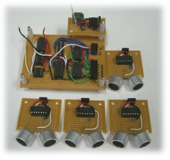
Fig. 4: picture of a the beacon main circuit with |
Preliminary experiment
We data-logged computed positions from a single module as it scanned a 9×9 grid of constant height and 151mm pitch. 200 samples were used to compute mean and error for each point in the grid. The experiment showed geometrical aberrations easily corrected using a simple lockup table (Fig. 5).

Fig. 5: Section of a virtual column made visible |
 Fig. 5: Computed positions/error (green) |
The average tracking precision was measured to be 18 mm along one axis, and as small as 4 mm along the other. A sample rate of 33 samples/sec could be achieved with this simple protocol (this sample rate does not depend on the number of receptors).
Conclusion and future works
We successfully demonstrated this cheap solution for virtual object collision avoidance in a plane about 4×4 meters wide. A 60 cm virtual column was situated in the center of this space (Fig. 5). Future work will aim to decrease directivity of the ultrasonic beams (Fig. 3) which was shown to limits the range of movements of the user as well as improving the triangulation algorithm in order to compute height.
References
- [1] Cassinelli, A. et al.. Augmenting spatial awareness with Haptic Radar. Tenth International Symposium on Wearable Computers (ISWC), Oct. 11-14, 2006, Montreux, Switzerland, pp.61-64 (2006).
- [2] Alois Ferscha et al., Vibro-tactile Space Awareness, Tenth International Conference on Ubiquitous Computing (Ubicomp 2008), Seoul Korea, September 21st – 24th (2008)
- [3] VIERJAHN Tom, Vibrotactile Feedback — A Fundamental Evaluation for Navigation in Virtual Studios, Laval Virtual 2009, Laval (France) (2009).
- [4] Namgyu Kim et al., 3-D Virtual Studio for Natural Inter-“Acting”, IEEE Transactions Systems, Man and Cybernetics, Part A: Systems and Humans, July 2006, Vol. 36, (4), pp.: 758-773 (2006)
- [5] Ramesh Raskar, Hideaki Nii, Bert Dedecker, Yuki Hashimoto, Jay Summet, Dylan Moore, Yong Zhao, Jonathan Westhues, Paul Dietz, John Barnwell, Shree Nayar, Masahiko Inami, Philippe Bekaert, Michael Noland, Vlad Branzoi, Erich Bruns, Prakash: lighting aware motion capture using photosensing markers and multiplexed illuminators, Proceedings of ACM SIGGRAPH, Volume 26(3), July (2007)
More information:
A. Zerroug, A. Cassinelli & M. Ishikawa, Virtual Haptic Radar, submitted poster for SIGGRAPH ASIA 2009, Yokohama. One page abstract.
Virtual Haptic Radar: touching ghosts – Ishikawa Watanabe Laboratory


